H3CNE综合实验之机器人
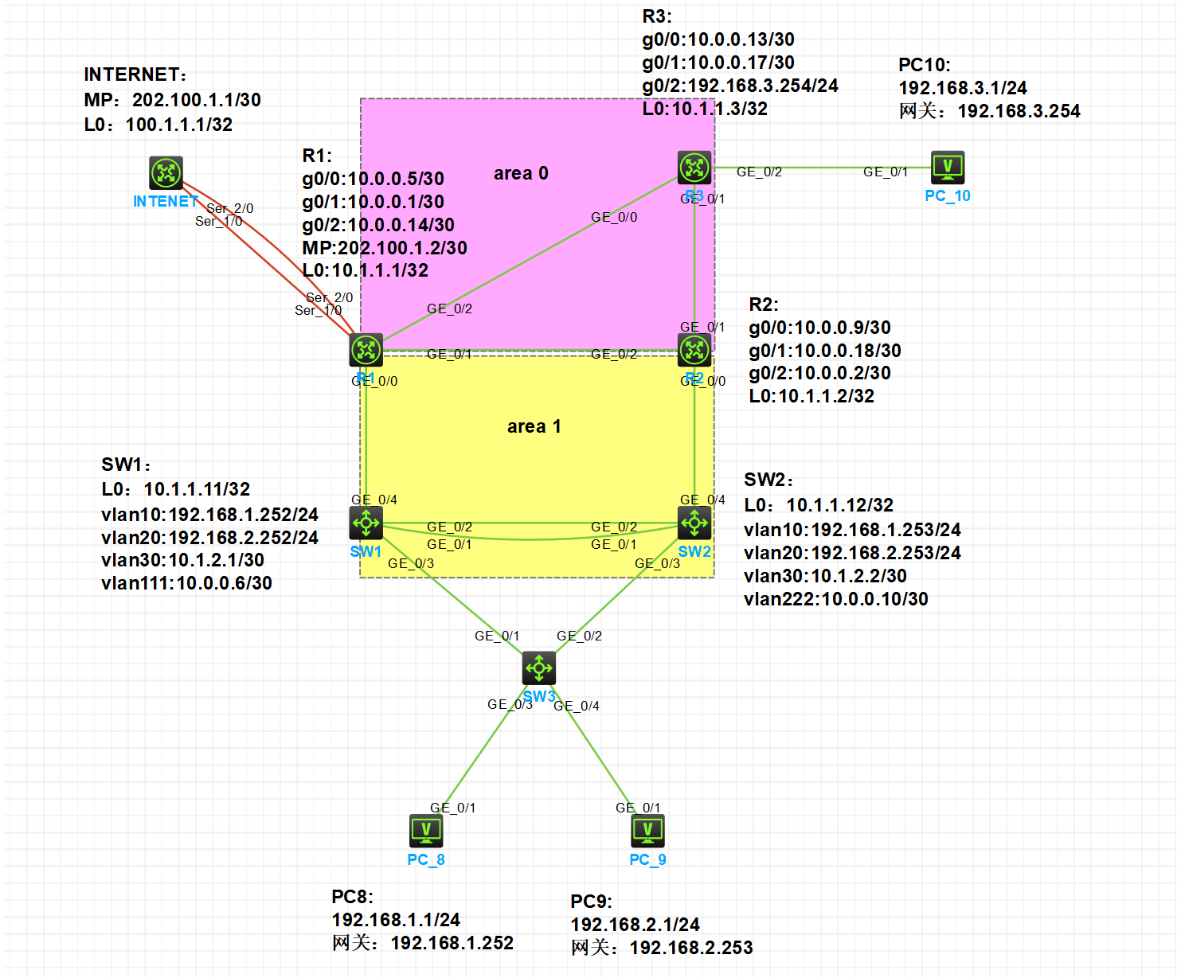
实验拓扑图
实验需求
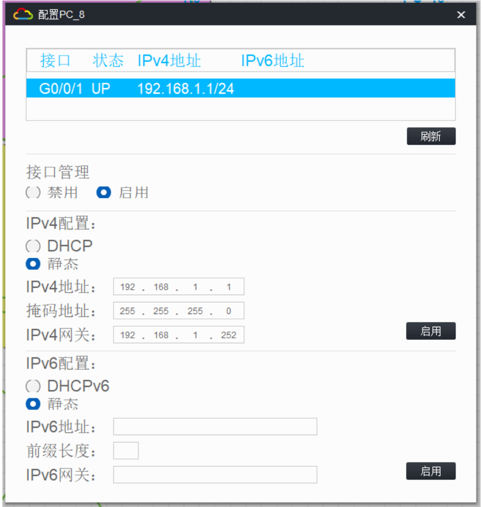
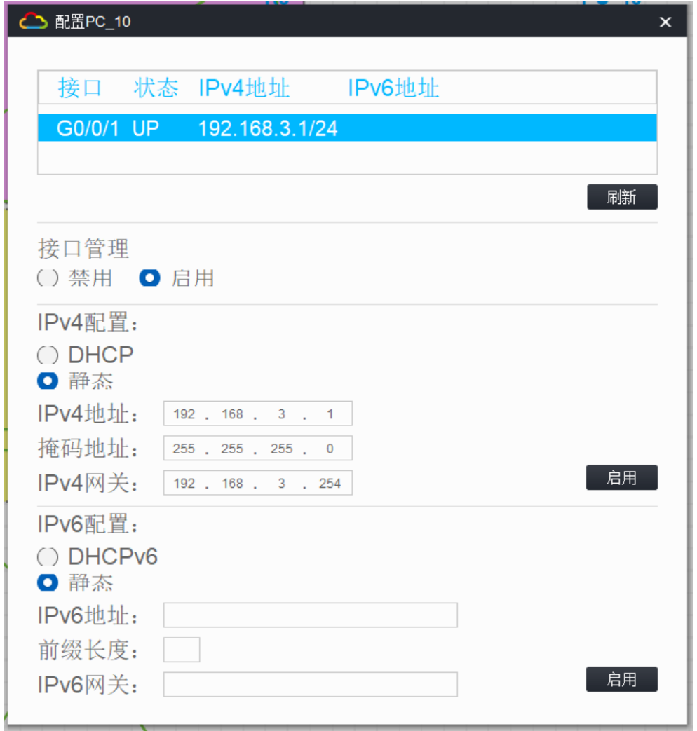
1.按照图示配置 IP 地址
2.SW1 和 SW2 之间的直连链路配置链路聚合
3.公司内部业务网段为 Vlan10 和 Vlan20;Vlan10 是市场部,Vlan20 是技术部,要求对 Vlan 进行命名以识别;
PC8 属于 Vlan10,PC9 属于 Vlan20,Vlan30 用于 SW1 和 SW2 建立 OSPF 邻居;
Vlan111 为 SW1 和 R1 的互 联 Vlan,Vlan222 为 SW2 和 R2 的互联 Vlan
4.所有交换机相连的端口配置为 Trunk,允许相关流量通过
5.交换区域配置生成树,要求SW2为根网桥,闭塞端口在SW3上
6.交换机连接 PC 的端口配置为边缘端口
7.按图示分区域配置 OSPF 实现公司内部网络全网互通,
R1和R2的环回口宣告进骨干区域;业务网段不允许出现协议报文(即配置静默接口)
8.R1 上配置默认路由指向互联网,并引入到 OSPF
9.R1通过双线连接到互联网,配置MP-GROUP,并配置双向chap验证
10.只有业务网段192.168.1.0/24和192.168.2.0/24的数据流可以通过R1访问互联网
11.R1开启TELNET远程管理,使用用户abc登录,密码123456.com
1.按照图示配置 IP 地址(略)
[R1]dis ip int b
*down: administratively down
(s): spoofing  (l): loopback
Interface           Physical Protocol IP address/Mask    VPN instance Description
GE0/0               up       up       10.0.0.5/30        --           --
GE0/1               up       up       10.0.0.1/30        --           --
GE0/2               up       up       10.0.0.14/30       --           --
GE5/0               down     down     --                 --           --
GE5/1               down     down     --                 --           --
GE6/0               down     down     --                 --           --
GE6/1               down     down     --                 --           --
Loop0               up       up(s)    10.1.1.1/32        --           --
Ser1/0              up       up       --                 --           --
Ser2/0              up       up       --                 --           --
Ser3/0              down     down     --                 --           --
Ser4/0              down     down     --                 --           --
[R2-LoopBack0]dis ip int b
*down: administratively down
(s): spoofing  (l): loopback
Interface           Physical Protocol IP address/Mask    VPN instance Description
GE0/0               up       up       10.0.0.9/30        --           --
GE0/1               up       up       10.0.0.18/30       --           --
GE0/2               up       up       10.0.0.2/30        --           --
GE5/0               down     down     --                 --           --
GE5/1               down     down     --                 --           --
GE6/0               down     down     --                 --           --
GE6/1               down     down     --                 --           --
Loop0               up       up(s)    10.1.1.2/32        --           --
Ser1/0              down     down     --                 --           --
Ser2/0              down     down     --                 --           --
Ser3/0              down     down     --                 --           --
Ser4/0              down     down     --                 --           --
[R3-LoopBack0]dis ip int b
*down: administratively down
(s): spoofing  (l): loopback
Interface           Physical Protocol IP address/Mask    VPN instance Description
GE0/0               up       up       10.0.0.13/30       --           --
GE0/1               up       up       10.0.0.17/30       --           --
GE0/2               down     down     192.168.3.254/24   --           --
GE5/0               down     down     --                 --           --
GE5/1               down     down     --                 --           --
GE6/0               down     down     --                 --           --
GE6/1               down     down     --                 --           --
Loop0               up       up(s)    10.1.1.3/32        --           --
Ser1/0              down     down     --                 --           --
Ser2/0              down     down     --                 --           --
Ser3/0              down     down     --                 --           --
Ser4/0              down     down     --                 --           --
[intenet-LoopBack0]dis ip int b
*down: administratively down
(s): spoofing  (l): loopback
Interface           Physical Protocol IP address/Mask    VPN instance Description
GE0/0               down     down     --                 --           --
GE0/1               down     down     --                 --           --
GE0/2               down     down     --                 --           --
GE5/0               down     down     --                 --           --
GE5/1               down     down     --                 --           --
GE6/0               down     down     --                 --           --
GE6/1               down     down     --                 --           --
Loop0               up       up(s)    100.1.1.1/32       --           --
Ser1/0              up       up       --                 --           --
Ser2/0              up       up       --                 --           --
Ser3/0              down     down     --                 --           --
Ser4/0              down     down     --                 --           --
[SW1]int l0
[SW1-LoopBack0]ip ad 10.1.1.11 32
[SW1]vlan 10
[SW1-vlan10]vlan 20
[SW1-vlan20]vlan 30
[SW1-vlan30]vlan 111
[SW1-vlan111]int vlan 10
[SW1-Vlan-interface10]ip ad 192.168.1.252 24
[SW1-Vlan-interface10]int vlan 20
[SW1-Vlan-interface20]ip ad 192.168.2.252 24
[SW1-Vlan-interface20]int vlan 30
[SW1-Vlan-interface30]ip ad 10.1.2.1 30
[SW1-Vlan-interface30]int vlan 111
[SW1-Vlan-interface111]ip ad 10.0.0.6 30
[SW1-Vlan-interface111]dis ip int b
*down: administratively down
(s): spoofing  (l): loopback
Interface                Physical Protocol IP Address      Description
Loop0                    up       up(s)    10.1.1.11       --
MGE0/0/0                 down     down     --              --
Vlan10                   down     down     192.168.1.252   --
Vlan20                   down     down     192.168.2.252   --
Vlan30                   down     down     10.1.2.1        --
Vlan111                  down     down     10.0.0.6        --
[SW2]int l0
[SW2-LoopBack0]ip ad 10.1.1.12 32
[SW2]vlan 10
[SW2-vlan10]vlan 20
[SW2-vlan20]vlan 30
[SW2-vlan30]vlan 222
[SW2-vlan222]int vlan 10
[SW2-Vlan-interface10]ip ad 192.168.1.253 24
[SW2-Vlan-interface10]int vlan 20
[SW2-Vlan-interface20]ip ad 192.168.2.253 24
[SW2-Vlan-interface20]int vlan 30
[SW2-Vlan-interface30]ip ad 10.1.2.2 30
[SW2-Vlan-interface30]int vlan 222
[SW2-Vlan-interface222]ip ad 10.0.0.10 30
[SW2-Vlan-interface222]dis ip int b
*down: administratively down
(s): spoofing  (l): loopback
Interface                Physical Protocol IP Address      Description
Loop0                    up       up(s)    10.1.1.12       --
MGE0/0/0                 down     down     --              --
Vlan10                   down     down     192.168.1.253   --
Vlan20                   down     down     192.168.2.253   --
Vlan30                   down     down     10.1.2.2        --
Vlan222                  down     down     10.0.0.10       --

2.SW1 和 SW2 之间的直连链路配置链路聚合
[SW1]int Bridge-Aggregation 1
[SW1-Bridge-Aggregation1]int range g1/0/1 to g1/0/2
[SW1-if-range]port link-aggregation group 1
[SW1-if-range]dis th
#
interface GigabitEthernet1/0/1port link-mode bridgecombo enable fiberport link-aggregation group 1
#
return
[SW2]interface Bridge-Aggregation 1
[SW2-Bridge-Aggregation1]int range g1/0/1 to g1/0/2
[SW2-if-range]port link-aggregation group 1
[SW2-if-range]dis th
#
interface GigabitEthernet1/0/1port link-mode bridgecombo enable fiberport link-aggregation group 1
#
return
3.划分VLAN
公司内部业务网段为 Vlan10 和 Vlan20;Vlan10 是市场部,Vlan20 是技术部,要求对 Vlan 进行命名以识别;
PC1 属于 Vlan10,PC2 属于 Vlan20,Vlan30 用于 SW1 和 SW2 建立 OSPF 邻居;
Vlan111 为 SW1 和 R1 的互 联 Vlan,Vlan222 为 SW2 和 R2 的互联 Vlan
(1)在SW3中给g1/0/3接口配置vlan10,给g1/0/4接口配置vlan20,并命名
[Sw3]vlan 10
[Sw3-vlan10]port g1/0/3
[Sw3-vlan10]name shichangbu
[Sw3-vlan10]dis th
#
vlan 10name shichangbu
#
return
[Sw3-vlan10]vlan 20
[Sw3-vlan20]port g1/0/4
[Sw3-vlan20]name jishubu
[Sw3-vlan20]dis th
#
vlan 20name jishubu
#
return
(2)在SW1的g1/0/4接口配置vlan111,在SW2的g1/0/4接口配置vlan222
[SW1]vlan 111
[SW1-vlan111]port g1/0/4
[SW2]vlan 222
[SW2-vlan222]port g1/0/4
4.所有交换机相连的端口配置为 Trunk,允许相关流量通过
[SW1]int Bridge-Aggregation 1
[SW1-Bridge-Aggregation1]port link-type trunk
Configuring GigabitEthernet1/0/1 done.
Configuring GigabitEthernet1/0/2 done.
[SW1-Bridge-Aggregation1]port trunk permit vlan 10 20 30
[SW1-Bridge-Aggregation1]int g1/0/3
[SW1-GigabitEthernet1/0/3]port link-type trunk
[SW1-GigabitEthernet1/0/3]port trunk permit vlan 10 20
[SW2]int Bridge-Aggregation 1
[SW2-Bridge-Aggregation1]port link-type trunk
Configuring GigabitEthernet1/0/1 done.
Configuring GigabitEthernet1/0/2 done.
[SW2-Bridge-Aggregation1]port trunk permit vlan 10 20 30
[SW2-Bridge-Aggregation1]int g1/0/3
[SW2-GigabitEthernet1/0/3]port link-type trunk
[SW2-GigabitEthernet1/0/3]port trunk permit vlan 10 20
[Sw3]int g1/0/1
[Sw3-GigabitEthernet1/0/1]port link-type trunk
[Sw3-GigabitEthernet1/0/1]port trunk permit vlan 10 20
[Sw3-GigabitEthernet1/0/1]int g1/0/2
[Sw3-GigabitEthernet1/0/2]port link-type trunk
[Sw3-GigabitEthernet1/0/2]port trunk permit vlan 10 20
5.交换区域配置生成树,要求SW2为根网桥,闭塞端口在SW3上
(1)查看现在的根网桥和闭塞端口
[SW1]dis stp
-------[CIST Global Info][Mode MSTP]-------Bridge ID           : 32768.56fa-9586-0500Bridge times        : Hello 2s MaxAge 20s FwdDelay 15s MaxHops 20Root ID/ERPC        : 32768.56fa-9586-0500, 0RegRoot ID/IRPC     : 32768.56fa-9586-0500, 0RootPort ID         : 0.0BPDU-Protection     : DisabledBridge Config-Digest-Snooping     : DisabledTC or TCN received  : 8Time since last TC  : 0 days 0h:45m:42s
[SW1]dis stp brief MST ID   Port                                Role  STP State   Protection0        Bridge-Aggregation1                 DESI  FORWARDING  NONE0        GigabitEthernet1/0/3                DESI  FORWARDING  NONE0        GigabitEthernet1/0/4                DESI  FORWARDING  NONE
[SW2]dis stp
-------[CIST Global Info][Mode MSTP]-------Bridge ID           : 32768.56fa-9aca-0600Bridge times        : Hello 2s MaxAge 20s FwdDelay 15s MaxHops 20Root ID/ERPC        : 32768.56fa-9586-0500, 18RegRoot ID/IRPC     : 32768.56fa-9aca-0600, 0RootPort ID         : 128.1409BPDU-Protection     : DisabledBridge Config-Digest-Snooping     : DisabledTC or TCN received  : 6Time since last TC  : 0 days 0h:46m:1s
[SW2]dis stp brief MST ID   Port                                Role  STP State   Protection0        Bridge-Aggregation1                 ROOT  FORWARDING  NONE0        GigabitEthernet1/0/3                DESI  FORWARDING  NONE0        GigabitEthernet1/0/4                DESI  FORWARDING  NONE
[Sw3]dis stp
-------[CIST Global Info][Mode MSTP]-------Bridge ID           : 32768.56fa-a098-0700Bridge times        : Hello 2s MaxAge 20s FwdDelay 15s MaxHops 20Root ID/ERPC        : 32768.56fa-9586-0500, 20RegRoot ID/IRPC     : 32768.56fa-a098-0700, 0RootPort ID         : 128.2BPDU-Protection     : DisabledBridge Config-Digest-Snooping     : DisabledTC or TCN received  : 10Time since last TC  : 0 days 0h:46m:25s
[Sw3]dis stp brief MST ID   Port                                Role  STP State   Protection0        GigabitEthernet1/0/1                ROOT  FORWARDING  NONE0        GigabitEthernet1/0/2                ALTE  DISCARDING  NONE0        GigabitEthernet1/0/3                DESI  FORWARDING  NONE0        GigabitEthernet1/0/4                DESI  FORWARDING  NONE
可以判断出根网桥为SW1,闭塞端口在SW3的g1/0/2上
要让SW2成为根网桥,那么就让SW2的优先级最小,改为4096
[SW2]stp priority 4096
[SW2]%Jul 15 19:19:05:488 2025 SW2 STP/6/STP_NOTIFIED_TC: Instance 0's port GigabitEthernet1/0/3 was notified a topology change.
再次查看SW2的STP运行状态,确认它成为根网桥
[SW2]dis stp brief MST ID   Port                                Role  STP State   Protection0        Bridge-Aggregation1                 DESI  FORWARDING  NONE0        GigabitEthernet1/0/3                DESI  FORWARDING  NONE0        GigabitEthernet1/0/4                DESI  FORWARDING  NONE
[SW2]dis stp
-------[CIST Global Info][Mode MSTP]-------Bridge ID           : 4096.56fa-9aca-0600Bridge times        : Hello 2s MaxAge 20s FwdDelay 15s MaxHops 20Root ID/ERPC        : 4096.56fa-9aca-0600, 0RegRoot ID/IRPC     : 4096.56fa-9aca-0600, 0RootPort ID         : 0.0BPDU-Protection     : DisabledBridge Config-Digest-Snooping     : DisabledTC or TCN received  : 7Time since last TC  : 0 days 0h:1m:29s
[SW1]dis stp brief MST ID Port Role STP State Protection0 Bridge-Aggregation1 ROOT FORWARDING NONE0 GigabitEthernet1/0/3 DESI FORWARDING NONE0 GigabitEthernet1/0/4 DESI FORWARDING NONE
[Sw3]dis stp brief MST ID Port Role STP State Protection0 GigabitEthernet1/0/1 ALTE DISCARDING NONE0 GigabitEthernet1/0/2 ROOT FORWARDING NONE0 GigabitEthernet1/0/3 DESI FORWARDING NONE0 GigabitEthernet1/0/4 DESI FORWARDING NONE
现在的闭塞端口在SW3的g1/0/1接口上,已经符合题目要求
6.交换机连接 PC 的端口配置为边缘端口
[Sw3]int g1/0/3
[Sw3-GigabitEthernet1/0/3]stp edg
Edge port should only be connected to terminal. It will cause temporary loops if port GigabitEthernet1/0/3 is connected to bridges. Please use it carefully.
[Sw3-GigabitEthernet1/0/3]stp edged-port
[Sw3-GigabitEthernet1/0/3]int g1/0/4
[Sw3-GigabitEthernet1/0/4]stp edg
Edge port should only be connected to terminal. It will cause temporary loops if port GigabitEthernet1/0/4 is connected to bridges. Please use it carefully.
[Sw3-GigabitEthernet1/0/4]stp edged-port
7.按图示分区域配置OSPF
(1)配置OSPF实现全网互通
[R1]ospf 1 router-id 10.1.1.1
[R1-ospf-1]area 0
[R1-ospf-1-area-0.0.0.0]network 10.1.1.1 0.0.0.0
[R1-ospf-1-area-0.0.0.0]network 10.0.0.1 0.0.0.0
[R1-ospf-1-area-0.0.0.0]network 10.0.0.14 0.0.0.0
[R1-ospf-1-area-0.0.0.0]dis th
#area 0.0.0.0network 10.0.0.1 0.0.0.0network 10.0.0.14 0.0.0.0network 10.1.1.1 0.0.0.0
#
return
[R1-ospf-1-area-0.0.0.0]quit
[R1-ospf-1]area 1
[R1-ospf-1-area-0.0.0.1]network 10.0.0.5 0.0.0.0
[R1-ospf-1-area-0.0.0.1]dis th
#area 0.0.0.1network 10.0.0.5 0.0.0.0
#
return
[R2]ospf 1 router-id 10.1.1.2
[R2-ospf-1]area 0
[R2-ospf-1-area-0.0.0.0]network 10.1.1.2 0.0.0.0
[R2-ospf-1-area-0.0.0.0]network 10.0.0.18 0.0.0.0
[R2-ospf-1-area-0.0.0.0]network 10.0.0.2 0.0.0.0
[R2-ospf-1-area-0.0.0.0]dis th
#area 0.0.0.0network 10.0.0.2 0.0.0.0network 10.0.0.18 0.0.0.0network 10.1.1.2 0.0.0.0
#
return
[R2-ospf-1-area-0.0.0.0]quit
[R2-ospf-1]area 1
[R2-ospf-1-area-0.0.0.1]network 10.0.0.9 0.0.0.0
[R2-ospf-1-area-0.0.0.1]dis th
#area 0.0.0.1network 10.0.0.9 0.0.0.0
#
return
[R3]ospf 1 router-id 10.1.1.3
[R3-ospf-1]area 0
[R3-ospf-1-area-0.0.0.0]network 10.0.0.13 0.0.0.0
[R3-ospf-1-area-0.0.0.0]%Jul 15 19:42:29:245 2025 R3 OSPF/5/OSPF_NBR_CHG: OSPF 1 Neighbor 10.0.0.14(GigabitEthernet0/0) changed from LOADING to FULL.[R3-ospf-1-area-0.0.0.0]network 10.0.0.17 0.0.0.0
[R3-ospf-1-area-0.0.0.0]network %Jul 15 19:42:58:947 2025 R3 OSPF/5/OSPF_NBR_CHG: OSPF 1 Neighbor 10.0.0.18(GigabitEthernet0/1) changed from LOADING to FULL.
192.168.3.254 0.0.0.255
[R3-ospf-1-area-0.0.0.0]network 10.1.1.3 0.0.0.0
[R3-ospf-1-area-0.0.0.0]dis th
#area 0.0.0.0network 10.0.0.13 0.0.0.0network 10.0.0.17 0.0.0.0network 10.1.1.3 0.0.0.0network 192.168.3.0 0.0.0.255
#
return
[SW1]ospf 1 router-id 10.1.1.11
[SW1-ospf-1]area 1
[SW1-ospf-1-area-0.0.0.1]network 192.168.1.252 0.0.0.255
[SW1-ospf-1-area-0.0.0.1]network 192.168.2.252 0.0.0.255
[SW1-ospf-1-area-0.0.0.1]network 10.1.2.1 0.0.0.0
[SW1-ospf-1-area-0.0.0.1]network 10.0.0.6 0.0.0.0
[SW1-ospf-1-area-0.0.0.1]dis th
#area 0.0.0.1network 10.0.0.6 0.0.0.0network 10.1.2.1 0.0.0.0network 192.168.1.0 0.0.0.255network 192.168.2.0 0.0.0.255
#
return
[SW2]ospf 1 router-id 10.1.1.12
[SW2-ospf-1]area 1
[SW2-ospf-1-area-0.0.0.1]network 192.168.1.253 0.0.0.255
[SW2-ospf-1-area-0.0.0.1]network 192.168.2.253 0.0.0.255
[SW2-ospf-1-area-0.0.0.1]network 10.1.2.2 0.0.0.0
[SW2-ospf-1-area-0.0.0.1]network 10.0.0.10 0.0.0.0
[SW2-ospf-1-area-0.0.0.1]dis th
#area 0.0.0.1network 10.0.0.10 0.0.0.0network 10.1.2.2 0.0.0.0network 192.168.1.0 0.0.0.255network 192.168.2.0 0.0.0.255
#
return
(2)业务网段不允许出现协议报文(即配置静默接口)
[SW1]ospf 1
[SW1-ospf-1]silent-interface vlan 10
[SW1-ospf-1]%Jul 15 20:00:12:803 2025 SW1 OSPF/5/OSPF_NBR_CHG: OSPF 1 Neighbor 192.168.1.253(Vlan-interface10) changed from FULL to DOWN.[SW1-ospf-1]silent-interface vlan 20
[SW1-ospf-1]%Jul 15 20:00:17:851 2025 SW1 OSPF/5/OSPF_NBR_CHG: OSPF 1 Neighbor 192.168.2.253(Vlan-interface20) changed from FULL to DOWN.[SW1-ospf-1]dis th
#
ospf 1 router-id 10.1.1.11silent-interface Vlan-interface10silent-interface Vlan-interface20area 0.0.0.1network 10.0.0.6 0.0.0.0network 10.1.2.1 0.0.0.0network 192.168.1.0 0.0.0.255network 192.168.2.0 0.0.0.255
#
return
[SW2]ospf 1
[SW2-ospf-1]silent-interface vlan 10
[SW2-ospf-1]%Jul 15 20:00:40:654 2025 SW2 OSPF/5/OSPF_NBR_CHG: OSPF 1 Neighbor 192.168.1.252(Vlan-interface10) changed from FULL to DOWN.[SW2-ospf-1]silent-interface vlan 20
[SW2-ospf-1]%Jul 15 20:00:44:159 2025 SW2 OSPF/5/OSPF_NBR_CHG: OSPF 1 Neighbor 192.168.2.252(Vlan-interface20) changed from FULL to DOWN.[SW2-ospf-1]dis th
#
ospf 1 router-id 10.1.1.12silent-interface Vlan-interface10silent-interface Vlan-interface20area 0.0.0.1network 10.0.0.10 0.0.0.0network 10.1.2.2 0.0.0.0network 192.168.1.0 0.0.0.255network 192.168.2.0 0.0.0.255
#
return
[R3]ospf 1
[R3-ospf-1]silent-interface g0/2
[R3-ospf-1]
[R3-ospf-1]dis th
#
ospf 1 router-id 10.1.1.3silent-interface GigabitEthernet0/2area 0.0.0.0network 10.0.0.13 0.0.0.0network 10.0.0.17 0.0.0.0network 10.1.1.3 0.0.0.0network 192.168.3.0 0.0.0.255
#
return
8.R1上配置默认路由指向互联网,并引入到OSPF
[R1]ip route-static 0.0.0.0 0 202.100.1.1
//后面的地址为对端IP地址
[R1-ospf-1]default-route-advertise
[R1-ospf-1]dis th
#
ospf 1 router-id 10.1.1.1default-route-advertisearea 0.0.0.0network 10.0.0.1 0.0.0.0network 10.0.0.14 0.0.0.0network 10.1.1.1 0.0.0.0area 0.0.0.1network 10.0.0.5 0.0.0.0
#
return
9.R1通过双线连接到互联网,配置MP-GROUP,并配置双向chap验证
[R1]int MP-group 1
[R1]local-user stw class network
New local user added.
[R1-luser-network-stw]password simple 123456
[R1-luser-network-stw]service-type ppp
[R1]int s1/0
[R1-Serial1/0]ppp mp MP-group 1[R1-Serial1/0]ppp chap user stw
[R1-Serial1/0]int s2/0
[R1-Serial2/0]ppp mp MP-group 1
[R1-Serial2/0]ppp chap user stw
[intenet]int MP-group 1
[intenet]local-user stw class network
New local user added.
[intenet-luser-network-stw]password simple 123456
[intenet-luser-network-stw]service-type ppp
[intenet-luser-network-stw]quit
[intenet]int s1/0
[intenet-Serial1/0]ppp mp MP-group 1[intenet-Serial1/0]ppp chap user stw
[intenet-Serial1/0]
[intenet-Serial1/0]int s2/0
[intenet-Serial2/0]ppp mp MP-group 1
[intenet-Serial2/0]ppp chap user stw
10.只有业务网段192.168.1.0/24和192.168.2.0/24的数据流可以通过R1访问互联网
根据要求配置EASYIP
[R1]acl basic 2000
[R1-acl-ipv4-basic-2000]rule  permit source 192.168.1.0 0.0.0.255
[R1-acl-ipv4-basic-2000]rule  permit source 192.168.2.0 0.0.0.255
[R1-acl-ipv4-basic-2000]quit
[R1]int MP-group 1
[R1-MP-group1]nat outbound 2000
11.R1开启TELNET远程管理,使用用户abc登录,密码abc
[R1]telnet server enable
[R1]local-user abc class manage
New local user added.
[R1-luser-manage-abc]password simple 123456.com
[R1-luser-manage-abc]authorization-attribute user-role level-15
[R1-luser-manage-abc]service-type telnet[R1]user-interface vty 0 5
[R1-line-vty0-5]authentication-mode scheme
[R1-line-vty0-5]user-role level-15
[R1-line-vty0-5]quit
测试效果
<H3C>telnet 10.1.1.1
Trying 10.1.1.1 ...
Press CTRL+K to abort
Connected to 10.1.1.1 ...******************************************************************************
* Copyright (c) 2004-2021 New H3C Technologies Co., Ltd. All rights reserved.*
* Without the owner's prior written consent,                                 *
* no decompiling or reverse-engineering shall be allowed.                    *
******************************************************************************Login: abc
Password:
<R1>
<R1>


上安装SVN Server和库权限设置问题)


