Title
题目
An End-to-End Geometry-Based Pipeline forAutomatic Preoperative Surgical Planning ofPelvic Fracture Reduction and Fixation
用于骨盆骨折复位与固定自动术前手术规划的基于几何的端到端流水线
01
文献速递介绍
骨盆骨折及其术前规划相关研究背景与本文方法 骨盆骨折是一种常见的严重创伤,主要由高能量外力导致[1],约占所有骨折类型的1%–3%。超过50%的骨盆骨折患者会出现并发症及多发损伤,包括闭合性颅脑损伤、盆腔血管出血和败血症等。其中,开放性骨盆骨折的致死率预计高达30%–50%[2]。多数情况下,骨折碎片移位越严重,盆腔出血的可能性越高,而盆腔出血正是骨盆骨折患者的首要死亡原因[3]。 骨折复位手术作为最常见的手术方式之一[4],是恢复骨盆骨折患者受损运动功能的有效治疗手段[5]。该手术通常分两步进行:1)将移位的骨折块复位至解剖学位置;2)采用螺钉、钢板等内固定器械对骨折部位进行固定,以维持复位后的稳定状态。若骨盆结构的解剖关系未完全恢复,或固定效果不可靠,可能引发创伤性骶髂关节/髋关节骨关节炎、骨折再次移位等远期疾病[6];患者还可能出现腰痛、步态异常或其他功能障碍等后遗症,严重影响工作与日常生活[7]。因此,骨折复位与内固定的术前规划至关重要。 然而,传统基于外科医生临床经验与操作习惯的规划方式存在诸多问题,如术中需反复调整方案、手术时间延长、术中透视辐射暴露过量等[8]。计算机辅助术前规划可有效规避上述问题,但在骨盆骨折场景中,骨折类型的多样性以及细小骨折碎片可能造成的干扰,导致骨骼分割与配准难度显著增加,为规划带来新挑战。现有计算机辅助系统多仅针对规划流程中的部分环节,且往往需要人工干预以确保规划精度。据作者所知,目前尚未有完整的端到端自动化术前规划方法被提出。 本文提出一种针对骨盆骨折全流程术前规划的全自动端到端计算机辅助方法,主要贡献包括三点:1)首个融合分割、复位与植入规划的骨盆骨折全自动端到端术前规划方法;2)提出一种新的两步式形态学自动配准方法,该方法结合对称特征与面特征,符合临床复位手术标准;3)提出一种迭代几何方法以计算近最优植入位置,并改进了带多约束的密集搜索优化算法以确定植入方向。 本方法是首个融合分割、复位与植入规划的骨盆骨折端到端术前规划方案,可大幅简化传统术前规划中繁琐的流程,为外科医生提供便利。
Abatract
摘要
Computer-assisted preoperative planning ofpelvic fracture reduction surgery has the potential toincrease the accuracy of the surgery and to reduce complications. However, the diversity of the pelvic fracturesand the disturbance of small fracture fragments present agreat challenge to perform reliable automatic preoperativeplanning. In this paper, we present a comprehensive andautomatic preoperative planning pipeline for pelvic fracturesurgery. It includes pelvic fracture labeling, reduction planning of the fracture, and customized screw implantation.First, automatic bone fracture labeling is performed basedon the separation of the fracture sections. Then, fracturereduction planning is performed based on automatic extraction and pairing of the fracture surfaces. Finally, screwimplantation is planned using the adjoint fracture surfaces.The proposed pipeline was tested on different types ofpelvic fracture in 14 clinical cases. Our method achieveda translational and rotational accuracy of 2.56 mm and3.31◦ in reduction planning. For fixation planning, a clinical acceptance rate of 86.7% was achieved. The resultsdemonstrate the feasibility of the clinical application of ourmethod. Our method has shown accuracy and reliabilityfor complex multi-body bone fractures, which may provideeffective clinical preoperative guidance and may improvethe accuracy of pelvic fracture reduction surgery.
计算机辅助骨盆骨折复位手术术前规划的研究 计算机辅助骨盆骨折复位手术术前规划,有望提高手术精准度并减少并发症。然而,骨盆骨折类型的多样性以及细小骨折碎片的干扰,为实现可靠的自动化术前规划带来了巨大挑战。 本文提出了一套全面的骨盆骨折手术自动化术前规划流程,涵盖骨盆骨折标记、骨折复位规划及个性化螺钉植入规划三个核心环节:首先,基于骨折断端的分离情况实现骨折自动标记;其次,通过骨折面的自动提取与配对完成骨折复位规划;最后,利用相邻骨折面进行螺钉植入规划。 该规划流程在14例临床病例的不同类型骨盆骨折中进行了测试。结果显示,在复位规划方面,平移精度与旋转精度分别达到2.56毫米和3.31度;在固定规划方面,临床接受率达86.7%。这些结果证实了该方法临床应用的可行性。此外,该方法对复杂多体骨骨折展现出良好的精准度与可靠性,有望为临床提供有效的术前指导,并提升骨盆骨折复位手术的精准度。
Method
方法
A. Overview
Fig. 1 shows the pipeline of our preoperative planningmethod. The input is the CT scan of the patient’s pelvicstructure. The outputs are the bone fragments, their spatiallocation, the implants, and their spatial location. And itconsists of 3 stages: Stage I is an automatic method forlabeling fracture fragments, which identifies and separatesall the bone fragments based on the improved adaptive-levelwatershed algorithm [35]. Subsequently, triangular meshes andpoint clouds of the fragments are generated as the input forthe subsequent stages; Stage II computes the target pose ofbone fragments by a proposed two-step surgical reductionmethod. The first step is the registration to the mirroredcontralateral bone based on the fast point feature histogram(FPFH) registration algorithm [36]. The second step is theautomatic registration based on fracture surfaces; Stage IIIis a novel personalized planning method of fracture fixationby screw implantation with several proposed geometry-basedalgorithms, based on the fracture surface computed in StageII. The planning of implantation includes the computation ofthe screws’ implanting amount, position, and direction.
A. 概述 图1展示了我们术前规划方法的流程。输入数据为患者骨盆结构的计算机断层扫描(CT)图像,输出结果包括骨折块及其空间位置、植入物及其空间位置。该流程包含3个阶段: 1. 阶段I(骨折块标记):一种自动化的骨折块标记方法,基于改进的自适应水平分水岭算法[35]识别并分离所有骨折块。随后,生成骨折块的三角网格和点云,作为后续阶段的输入数据; 2. 阶段II(骨折复位规划):通过提出的两步手术复位方法计算骨折块的目标位姿。第一步是基于快速点特征直方图(FPFH)配准算法[36],将骨折块与镜像对侧骨骼进行配准;第二步是基于骨折面的自动配准; 3. 阶段III(螺钉植入规划):一种新颖的个性化骨折固定规划方法,基于阶段II计算得到的骨折面,采用多种提出的几何算法规划螺钉植入方案。植入规划包括计算螺钉的植入数量、位置和方向。
Conclusion
结论
In this work, we proposed an automatic preoperative planning method for pelvic fracture reduction surgery that consistsof three stages. The fracture fragment labeling method is basedon the separation of fracture sections. For the reduction planning, a two-step registration is used to compute the anatomicalposition of the fractured bones. Finally, an implantation planof the number, positions, and directions of implanted screwsis generated based on the adjoint fracture faces. All threestages of preoperative planning of pelvic fracture surgery canbe automatically performed with little or no user interaction.Experiments on clinical datasets from a publicly availabledataset demonstrate the feasibility of our method. More clinical data will be collected to verify the stability and improvethe detailed design of the pipeline, and to extend our methodto other types of fractures in the future.
本文研究内容摘要 本研究提出一种适用于骨盆骨折复位手术的自动术前规划方法,该方法包含三个阶段: 1. 骨折块标记阶段:基于骨折断面分离实现骨折块标记; 2. 复位规划阶段:采用两步配准法计算骨折块的解剖学位置; 3. 植入规划阶段:依据相邻骨折面生成螺钉植入数量、位置及方向的规划方案。 骨盆骨折手术术前规划的上述三个阶段均可自动完成,几乎无需或完全无需用户干预。 基于公开数据集的临床数据实验验证了该方法的可行性。未来,研究团队将收集更多临床数据,以验证该方法的稳定性、改进流程的细节设计,并将其扩展应用于其他类型的骨折(手术术前规划)。
Figure
图
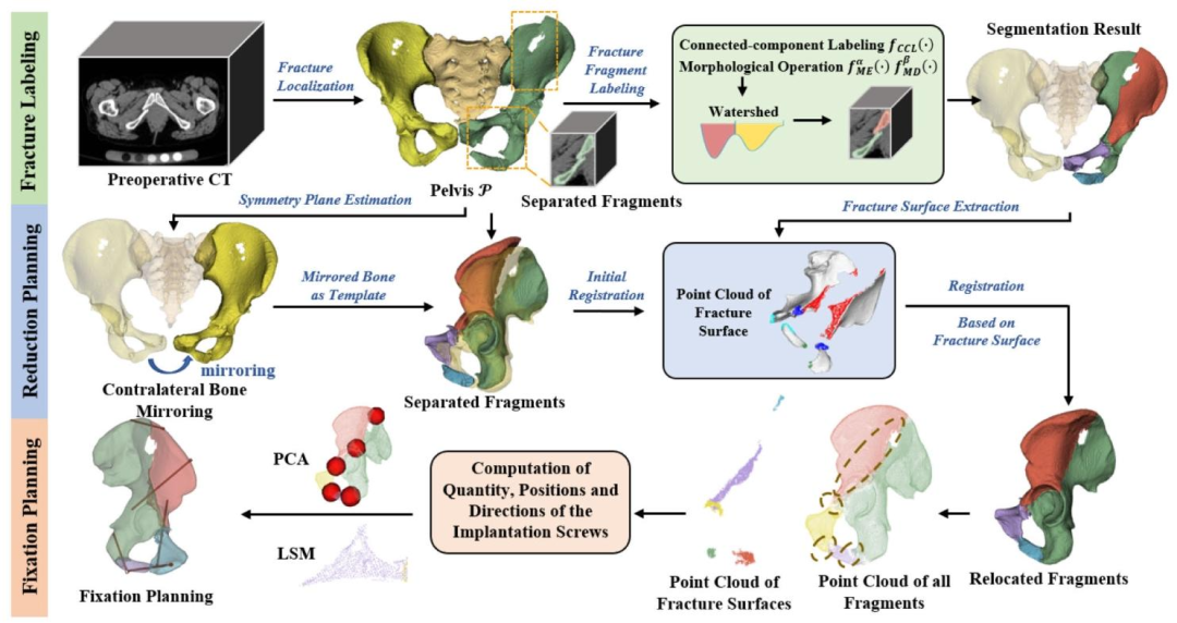
Fig. 1. Pipeline of the preoperative planning method for pelvic fracture surgery. StageI: Bone Fracture Labeling; StageII: Fracture ReductionPlanning; StageIII: Fixation Planning
图1 骨盆骨折手术术前规划方法流程 该流程分为三个阶段: - 第一阶段(Stage I):骨折标记(Bone Fracture Labeling) - 第二阶段(Stage II):骨折复位规划(Fracture Reduction Planning) - 第三阶段(Stage III):固定规划(Fixation Planning)
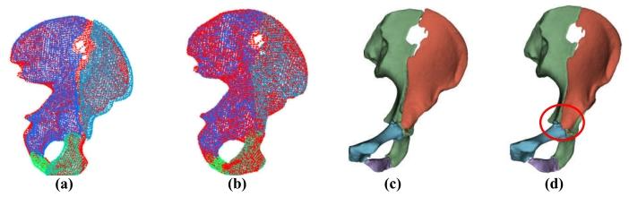
Fig. 2. Illustration of the effect of coarse registration: (a)-(b) relativeposition of P T (red) and P1, · · · ,Pn before and after registration;(c)-(d) F1, · · · , Fn before and after registration.
图2 粗配准效果示意图 - (a)-(b):配准前后,目标骨盆((P_T),红色标记)与待配准骨盆((P_1,···,P_n))的相对位置关系; - (c)-(d):配准前后,待配准骨盆对应的骨折面((F_1,···,F_n))的状态变化。
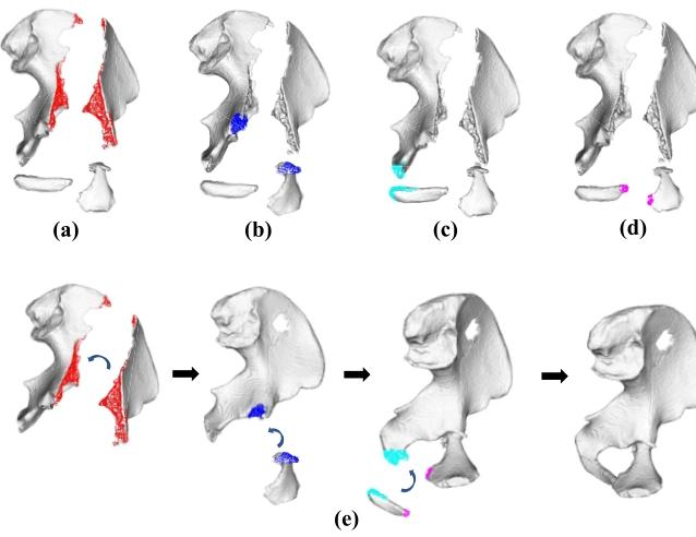
Fig. 3. Registration based on pairwise point clouds. (a)-(d) Pairwise pointclouds of fracture surfaces. Each color of the point cloud corresponds toa matching pair of point clouds; (e) The progress of the registration basedon the point clouds of the fracture surface.
图3 基于点云配对的配准过程 - (a)-(d):骨折面的点云配对结果,点云中的每种颜色对应一组匹配的点云对; - (e):基于骨折面点云的配准进度(或动态过程)展示。
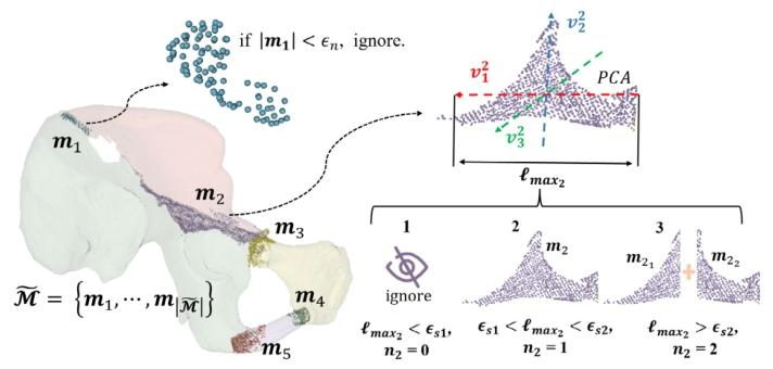
Fig. 4. Illustration of the computation of the number of implanted screwsfor fragments m1 and m2.
图4 骨折块m₁与m₂的植入螺钉数量计算示意图
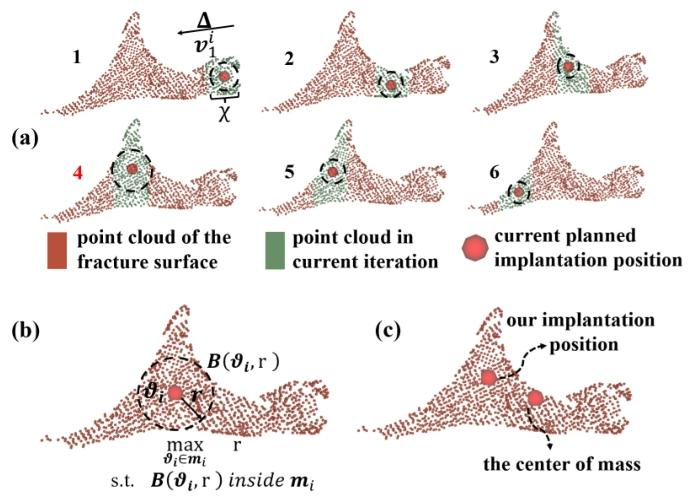
Fig. 5. Illustration of the computation of the positions of the implantedscrews. (a) iterative computation process; (b) the ideal implantationposition; (c) a comparison of our planned position and the center of mass.
图5 植入螺钉位置计算示意图 - (a):螺钉位置的迭代计算过程(展示通过多轮迭代优化,逐步逼近最优螺钉位置的动态步骤); - (b):螺钉的理想植入位置(呈现符合临床固定需求、兼顾稳定性与安全性的目标位置); - (c):本文规划的螺钉位置与质心位置的对比(通过直观对比,验证所提方法规划位置相较于质心位置的合理性与优势)。
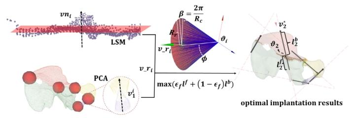
Fig. 6. Illustration of the computation of the directions of the implantedscrews. For an implantation position, an initial direction vri is generatedaccording to the point cloud in and around the fracture surface. Thenwith vri , an improved dense search method based on [40] is proposed toobtain the optimal trajectory
图6 植入螺钉方向计算示意图 对于某一植入位置,首先根据骨折面内部及周边的点云生成初始方向(v_r_i);随后以(v_r_i)为基础,采用一种基于文献[40]改进的密集搜索方法,最终确定螺钉的最优植入轨迹。
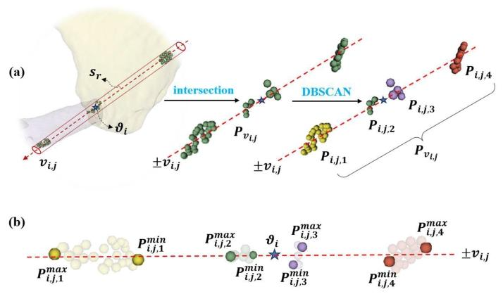
Fig. 7. Illustration of: (a) the extract and the clustering of the points insidethe cylinder passing through ϑi with vi,j as the axis, sr as the radius; (b)computation of the closest and farthest points from ϑi in each category,where πmini,j,1 = p min i,j,1 − ϑi , πi max ,j,1 = p max i,j,1 − ϑi
图7 相关计算过程示意图 - (a):以(v{i,j})为轴线、(s_r)为半径,对穿过点(\vartheta_i)的圆柱体内的点进行提取与聚类(展示从特定几何范围内筛选目标点,并通过聚类算法分组的过程); - (b):计算每类点中与(\vartheta_i)距离最近和最远的点,其中(\pi{i,j,1}^{\text{min}} = p{i,j,1}^{\text{min}} - \vartheta_i),(\pi{i,j,1}^{\text{max}} = p_{i,j,1}^{\text{max}} - \vartheta_i)(呈现对聚类后各组点的距离量化计算,明确近点与远点相对于(\vartheta_i)的偏移关系)。
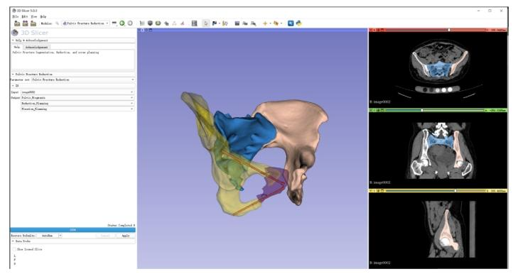
Fig. 8. Our preoperative planning system on 3D Slicer is implemented inan extensible module that allows for advanced functionality in fragmentlabeling, reduction planning, and screw implantation planning. The inputis a preoperative CT image. It allows visualization of the post-reductionpositions of the individually labeled fragments and the position andlocation of the screws (in red)
图8 基于3D Slicer的术前规划系统 该术前规划系统在3D Slicer平台上以可扩展模块形式实现,具备骨折块标记、复位规划及螺钉植入规划的高级功能。系统输入为术前CT图像,可可视化展示:经单独标记的各骨折块复位后的位置,以及螺钉(红色标记)的植入位置与方位。
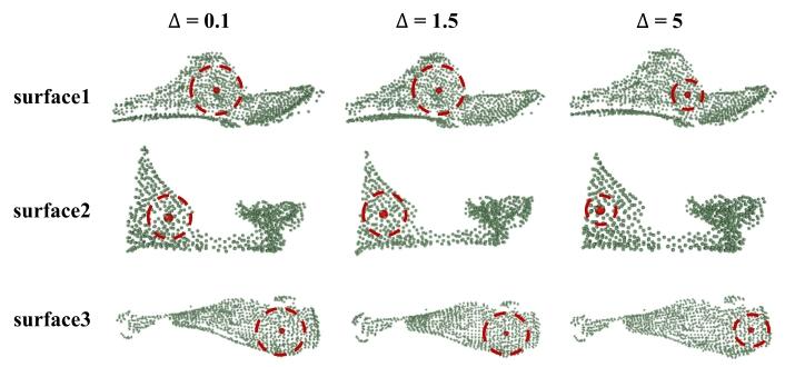
Fig. 9. Illustration of the results of the sensitivity study on the step size ∆for computing Chebyshev Center with Equations 14-18. The maps showthe three fracture surfaces from different pelvis in different locations,scales, and shapes
图9 基于式(14-18)计算切比雪夫中心时步长∆的敏感性研究结果示意图 图中展示了来自不同骨盆、处于不同位置、具有不同尺度与形态的三个骨折面,用于呈现步长∆的变化对切比雪夫中心计算结果的影响(以此验证步长参数选择对算法稳定性或精度的敏感程度)。
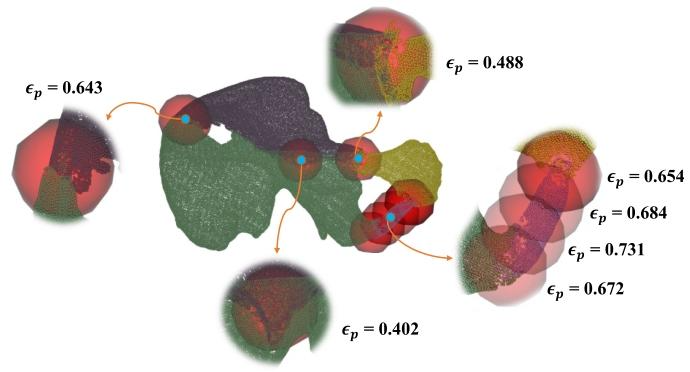
Fig. 10. The results of the exploratory study on principal componentcontribution values in different regions of the pelvis
图10 骨盆不同区域主成分贡献值的探索性研究结果
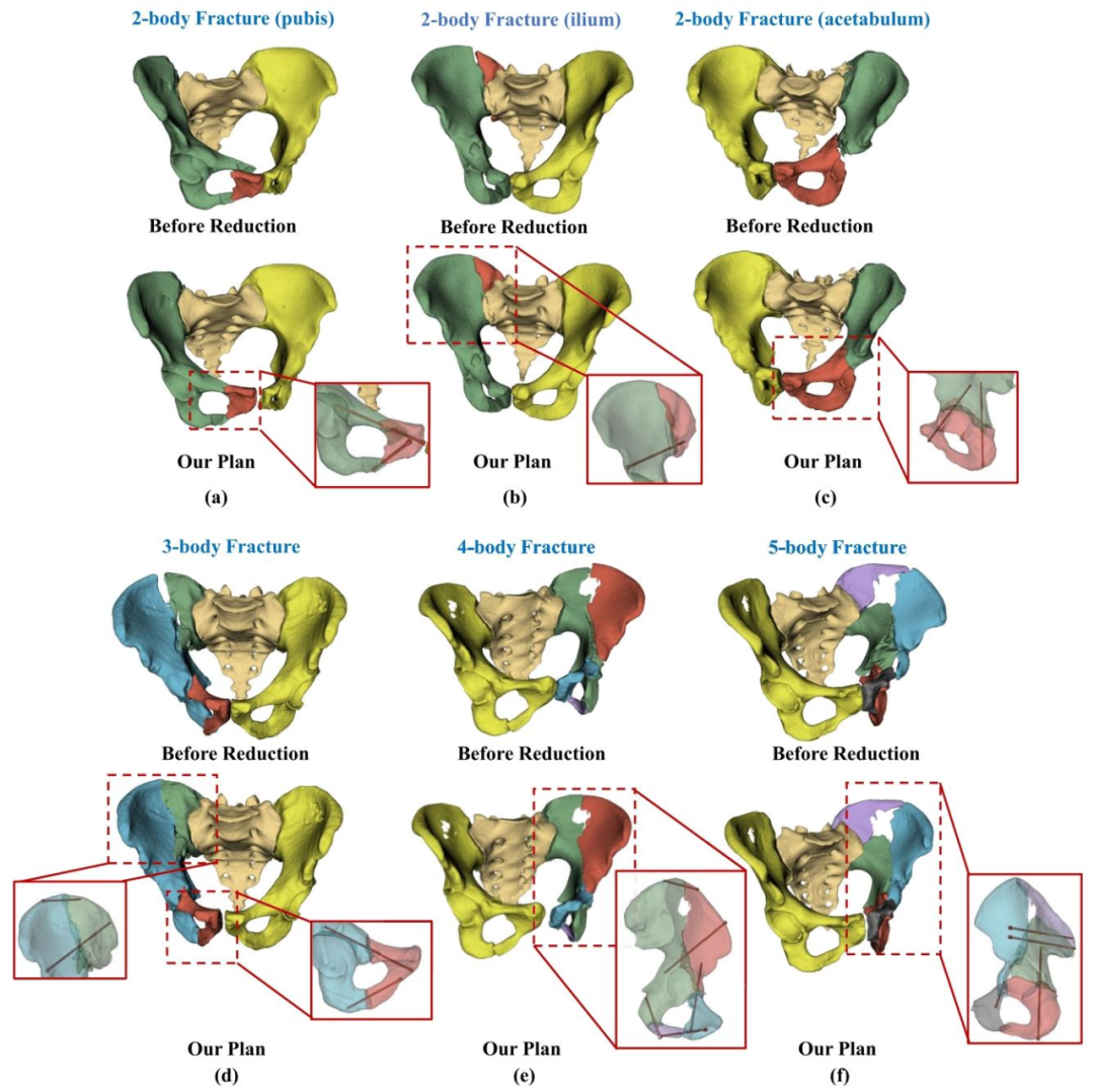
Fig. 11. Examples of various types of pelvic fractures and our preoperative planning results. (a)2-body fracture of the pubis; (b)2-body fracture ofthe ilium; (c)2-body fracture of the acetabulum; (d)3-body fracture of multiple structures; (e)4-body fracture of multiple structures; (f) 5-body fractureof multiple structures
图11 不同类型骨盆骨折及术前规划结果示例 - (a):耻骨二体骨折; - (b):髂骨二体骨折; - (c):髋臼二体骨折; - (d):多结构三体骨折; - (e):多结构四体骨折; - (f):多结构五体骨折。
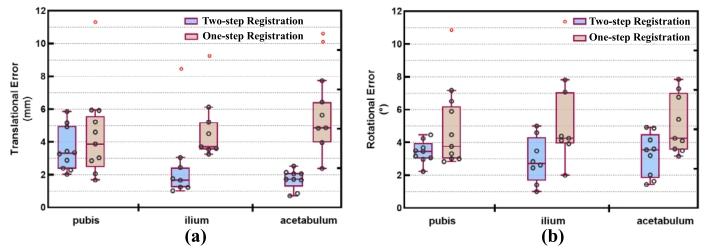
Fig. 12. The reduction error of one-step registration as compared toour two-step registration method for the pubis, ilium, and acetabulum:(a) translational error; (b) rotational error.
图12 耻骨、髂骨及髋臼部位一步配准与本文两步配准方法的复位误差对比 - (a):平移误差(展示在耻骨、髂骨、髋臼三个解剖部位,一步配准与两步配准分别产生的平移方向误差数值对比,直观呈现两步配准在降低平移偏差上的优势); - (b):旋转误差(呈现上述三个部位中,两种配准方法对应的旋转方向误差差异,体现两步配准在提升旋转复位精度方面的效果)。
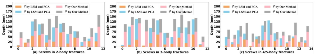
Fig. 13. l f , lb from vr and our method in Section III-D.3: (a) 2-body, (b) 3-body,and (c) 4/5-body fractures.
图13 基于初始方向(v_r)与本文第III-D.3节方法的(l_f)、(l_b)对比:(a)二体骨折,(b)三体骨折,(c)四体/五体骨折
Table
表
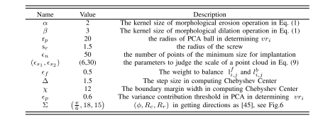
table i parameter setting in the experiment of screw implantation planning
表 1 螺钉植入规划实验中的参数设置
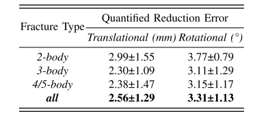
table ii reduction error of clinical cases
表2 临床病例的复位误差
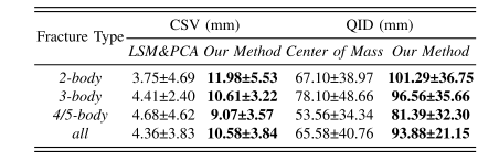
table iii the contrast experiment on qid and csv
表3 QID与CSV的对比实验
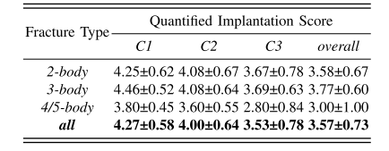
table iv results of the likert rating scale survey
表 4 李克特量表调查结果
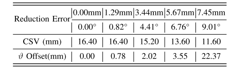
table v the quantified outcomes of implantation planning in a case with different reduction errors. csv was measured with a resolution of 0.40mm
表5 不同复位误差病例中植入规划的量化结果 临床安全价值评分(CSV)的测量分辨率为0.40毫米。
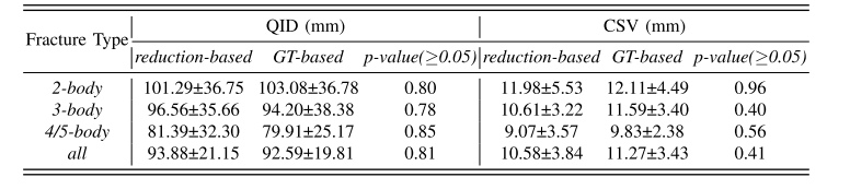
table vi the quantified effects of the reduction planning on implantation
表6 复位规划对植入规划的量化影响


。)


)
)


